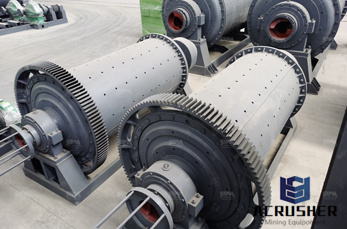
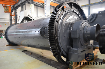
structure of ball mill
Ball Mill Basic structure PTC Creo Parametric 3D CAD A ball mill is a type of grinder used to grind and blend materials for use in mineral dressing processes, paints, pyrotechnics, ceramics and

 WhatsApp)
Ball Mill Basic structure PTC Creo Parametric 3D CAD A ball mill is a type of grinder used to grind and blend materials for use in mineral dressing processes, paints, pyrotechnics, ceramics and
Nov 18, 2008#0183;#32;Equations of the design By knowing the capacity quot;Cquot; {ton} of the feed; we can get approximately the length quot;Lquot; {mm} and diameter quot;Dquot; {mm} of the batch ball mill, form **D = *(C) + **L= *(C) + 1854 Volume of mill = ^2 The bulk volume of balls charge ratio to the volume of mill is known as {Filling ratio} and its range is {3045%} ^2 _____ ** Note: There is not
Nov 13, 2014#0183;#32;Offical website: Alibaba website: Product webpage:
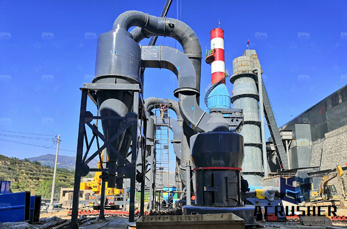
Keywords: Ball mills, grinding circuit, process control. I. Introduction Grinding in ball mills is an important technological process applied to reduce the size of particles which may have different nature and a wide diversity of physical, mechanical and chemical characteristics. Typical examples are the various ores, minerals, limestone, etc.
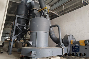
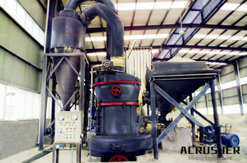
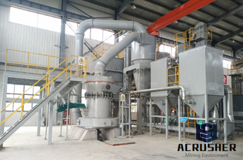
ball mill structure and working nigeria. Ball millYouTube. 3D demo of ball mill structure and working principle by Henan Bailing. 1 58. Coal ball mill grinding site with dust collector by Baichy mining equipment crusher grinder separator.
3d Demo Of Ball Mill Structure And Working Principle Youtube. Dec 02 2014 starting a 6kv 3ph 2200 kw 1000 rpm slipring motor for a cement ball mill duration 351 yves mamin 501825 views. Get Price. Planetary Ball Mill Pm 100 Retsch Highest Fineness.
Ball Mills are generally used to grind material 1/4 inch and finer, down to the particle size of 20 to 75 microns. To achieve a reasonable efficiency with ball mills, they must be operated in a closed system, with oversize material continuously being recirculated back into the mill to be reduced.
3d ball mill(3D Reactor) that is our patent. our 3d ball mill(3D REACTOR) makes it possible that 2d ball mill cannnot achieve. It realizes different homogeneity mixture of nonsolidification, a single peak, a crush thing, specific gravity and the viscosity. Product Line up
The substructure method is used for dynamic analysis of the ball mill foundation, that is, the structure and soil are considered as two parts separately. The structure (mat foundation and piers
ball mill for ore ginding. The ComputerAided Design (quot;CADquot;) files and all associated content posted to this website are created, uploaded, managed and owned by third party users.
MSKSFM3 is a compact highspeed ball mill with the 3D movement for making the small quantity of samples at easy and fast. It has higher impact energy created by rotation, vibration, and oscillation with frequency up to 1200RPM with a twoyear warranty. The MSKSFM3 can be used in either dry or wet methods to mill materials and mix all kinds of solids, suspended liquids, and pastes with
Aug 01, 2019#0183;#32;[email protected] are prepared via a ball milling method and insitu reduction treatment. Interconnected 3D BNNS networks formed by thermally sintered AgNPs structures. The silver bridges serve as thermal transport junctions in the 3D filler network. The mechanical and thermal stability of composites are improved simultaneously.
Basic Structure Of A Ball Mill System Ball mill basic structure 3d cad model library ball mill is a type of grinder used to grind and blend materials for use in mineral dressing processes, paints, pyrotechnics, ceramics and print workbench community log in . Structure and working principle of ball mill Structure and working principle of ball mill.
Jun 26, 2017#0183;#32;Ball Nose Milling Without a Tilt Angle. Ball nose end mills are ideal for machining 3dimensional contour shapes typically found in the mold and die industry, the manufacturing of turbine blades, and fulfilling general part radius properly employ a ball nose end mill (with no tilt angle) and gain the optimal tool life and part finish, follow the 2step process below (see Figure 1).
WhatsApp)